|

|
|
in cm / kgs |
inches/lbs |
|
Size of top platen |
80 x 100 cm |
31.5" x 39" |
|
Size of bottom platen |
85 x 105 cm |
33.5" x 41" |
|
Maximum pressure between platens |
25000 kgs |
55000 lbs |
|
Maximum opening between platens |
14 cm |
5.5" |
|
Total length |
232 cm |
91" |
|
Total width |
120 cm |
47" |
|
Total height |
193 cm |
76" |
|
Voltage (single phase AC) |
230 Volt |
on request110 V |
|
Working height |
85 cm |
33" |
|
Weight |
1100 kg |
2420 lbs |
|
Dimensions of press with standard packing on pallet. WxLxH |
125 x 240 x 210 cm |
49" x 94" x 83" |
|
Weight of press with standard packing |
1200 kg |
2640 lbs |
|
Crate dimensions WxLxH |
125 x 240 x 210 cm |
49" x 94" x 83" |
|
Weight of press in crate |
1250 kg |
2750 lbs |
This is a highly professional press for printing lino- and woodcuts. The upper-platen is moved vertically by a hydraulic cylinder. These presses do resemble to the old hand presses (Columbian, Albion, Washington, etc.). In fact technically there are many similarities. The major difference however is the system to apply force to the top platen. The old presses were all equipped with ingeneous lever systems in order to use human strength as efficient as possible. Modern platen presses can be equipped with hydraulic systems which makes it possible to exercise forces that were never possible with hand presses.
The olds presses were limited in size because of the limitations of the technical systems in those days. It took much strenght of the printer to print a full size paper. One has to realize that normally a printer only dealt with a page of set type. If that printer had to print a woodcut with the same size, he would need even more strength. The part of a woodcut that is in actual contact with the paper is generally bigger that the part of a page set in type that is in contact with the paper.
Polymetaal adapted the old presses to modern techniques. We came up with the VPL-80x100, but in four variations. This press, the VPLER-80x100 has a slidable lower platen, making it much easier to ink and apply the printing forme. The printing forme can be fixed on the lower platen with the aid of screw holes on the circumference of the lower platen.. The maximum space between the two platens is 14 cm. There is no need to go up and down those 14 cm every time you print. The vertical momevent of the top platen can be limited with the two screws visible on top of the press. The pressure is given by an electric hydrualic pump that has a work pressure of 700 bar. The pump has a three-position-valve. The maximum pressure that can be realised with this press is 25,000.-- kgs. All presses have some features in common;
- The platens are made of very thick welded steel. They resist much more pressure than the cast iron platens in the old days. The platens have been treated in an oven to release all inside tensions and surface planed afterwards. This guarantees that the platens will never change shape.
- Through a special design, damage to the upper platen is prevented if it is lopsided as a result of incorrect use.
- De vertical movement of the upper platen is driven by a hydraulic cylinder with a maximum capacity of 25.000 kgs.
- The maximum clearing between the platens is 14cm. The distance between the platens can be set to any lower value by adjusting two vertical screws. The printing speed is improved if this value is not moore than needed for the printing job.
Explanation of the three way hydraulic valve of the VPLER and VPLEV platen presses.
These electric hydraulic presses are powered by an electric motor that drives an "oil-pump". This oil pump activates the hydraulic cylinder that in its turn, moves the platen up and down. The action of this hydraulic cylinder is controlled by a manually operated three way valve.
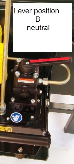
- When the machine is turned on, it is advisable to have the lever of the valve in neutral position. (on the images below; position B). However, if you do not work on the machine, the pump will only pump the oil round in the system, so it is better to turn off the motor.
- The hydraulic pump is activated by turning the switch, that is attached to the electric motor. If the lever of the valve is in neutral position, nothing will happen. There will be only a certain vibration of the hydraulic pump.
- When the lever of the valve is turned into "position C", the platen will come down slowly. Please be careful when you do this. Verify that there are no strange opjects between the two platens. If there are such objects, this may lead to damage of the press and even accidents. The platen will continue to go down until it reaches the "printing sandwich" or the lower platen. As soon as it hits the sandwich the oil pressure in the system will rise, as can be read on the gauge. The pressure can go up until the maximum allowable pressure is reached (700 bar). At this point the top platen exercices a force of 25 tons (25.000 kgs) The pressure will never exceed this point because an "overflow" valve starts to function. (the overflow valve is indicated on the image).
- This overflow valve will in this system also be used as a means to limit the pressure, if that is necessary for a certain print. If a print is small, only a fraction of the 25 tons is needed. Also the proportion of the surface that is actually in contact with the paper is important. A print with only lead type needs far less pressure than a general woodcut of the same size.
- In a try out session the correct pressure should be determined. The overflow valve needs to be adjusted then in such a manner that it starts overflowing when the desired pressure is reached.
- If this is accomplished the whole series of that same print can be done without re-adjusting the pressure between the printing cycles.
- When the top platen reached the printing sandwich, and the desired pressure is reached, the overflow valve will start its function. At this point it is wise to switch the valve back into neutral position. In this neutral position the system keeps its pressure. If the pump remains too long in the "overflow mode" it may lead to overheating of the oil. In the neutral position the oil will not heat up! Sometimes it it better for the transfer of the ink to the paper if the pressure is maintained for a few seconds. This system allows you to do that.
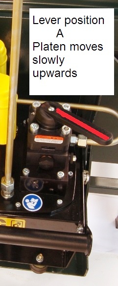
- When the platen must come up again, turn the valve slowly into position A. This needs to be done slowly, especially if high pressures are involved. A sudden release of the pressure produces a "shock" in the system. This is not dangerous in any way, it is only uncomfortable. (the gauge is filled with oil, to neutralize the shock in its mechanism).
- The platen will go up until it reaches the long screws (metric 16mm). This screws can be turned up and down. (you will have to climb on the machine to do it however.) These two screws have to be always on equal hights. If your printing sandwich is normally only 3 cm thick, you do not need the maximum space of 14 cm between the platens. This will only be inefficient. With the two screws at the right position you can limit the upwards movement of the top platen.
 |