Ensamblar y desensamblar los prensas grabado
Polymetaal serie JW
Read instructions completely before initiating
disassembly
Normally Polymetaal sends these bigger presses completely
assembled to the client. There are some reasons to do it this
way;
- We are completely sure that the press is assembled in a correct way
and that all the parts are there.
- Only in this manner we can give a garantee of ten years to these
bigger presses.
Of course it is allowed to order the press in parts and assemble it
yourself, but then Polymetaal is not responsible for the result of
that assembly.
Another possibility is that an employee of our company comes to
deliver the press to you personally and assembles it as well. This
way you have your ten years garantee, but at some extra costs. You
can always ask us to make a quote on this.
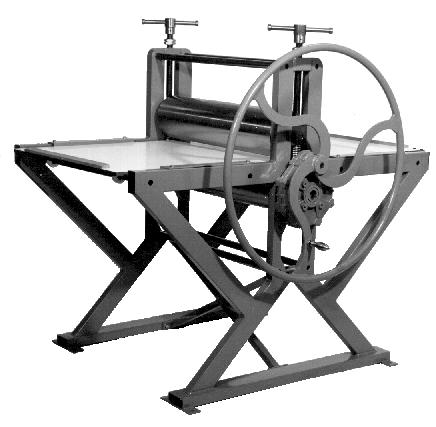 Etching
press JW-80
Etching
press JW-80
So, perhaps you received the press in parts. If so, proceed to the
paragraph that deals with the assembly of the press.
If you received the press assembled, and you have to take it apart
first, please start reading here;
Disassembly of etching press JW series
In this description we refer to the next image "cross section
etching press JW-series". This "drawing" is not on scale and is
adapted in such a way that it gives a clearer understanding of the
construction of these presses;
- The press is probably fixed on a pallet and packed with
plastic. Take the plastic of and release the press from the
pallet. Leave the plastic to protect the cylinders.
- If the bed is situated between the two cylinders, take it
out.
- Make, in one way or another, a fixed point above the press
that allows you to hoist the cilinders. Bring a tackle in that
fixed point. Important; see Nr. 14
- Release the spindles (1) on top the upper cylinder, and take
the spindles out of the side frames.
- Take the hand wheel (16) from the gear box (18). There is a
small screw in the hub oh the wheel that has to be released
first.
- Take the gear box (18) from the lower cylinder (7). For this
you need the special hexagonal key (9) that is fixed to the hand
wheel with tape. This key is very short on one end and this allows
you to release the two screws M10 (8)(cyl.head screws with inside
hex.) from the gear box.
- Take the key (19) and the circlips(20)(also from the opposite
end) from the lower cylinder.
- Take the pressure blocks (14) and (if present) the cardboard
pile (15) from the press.
- Fix a good rope at the middle of the upper cylinder and hoist
it with the tackle to such a level that it permits you to take the
two springs (N) out. Now you can lower again the upper cylinder
and take the rope off.
- Use a good and strong
 rope
to connect the two cylinders to eachother and to the tackle, like
this drawing shows; For reasons of simplicity the side frames are
not drawn.
rope
to connect the two cylinders to eachother and to the tackle, like
this drawing shows; For reasons of simplicity the side frames are
not drawn.
- Try to hoist these to cylinders together, untill the press as
a whole is almost lifting from the ground.
- Release the screws of the round bars between the frames. There
are eight screws to be released (13) M12x45 (ins.hex cyl.head) and
eight screws M8x20 (ins.hex cyl.head) which are hidden behind
slotted holes on the inside of the side frames. These screws keep
the round bars in place that carry the white plastic rollers.
- Release the cyl.head screws M10x40 (11) and the hex.bolts M10
(24) that keep the cross in place.
- Now everything is ready to take the side frames away. Be very
careful. The two cylinders are connected to the tackle. The weight
varies depending upon which press it is in the JW series. The
weight may be something like 300kgs. Be sure that the rope, tackle
and fixing point can have this weight without any problems.
(POLYMETAAL does NOT use rope to connect the two cylinders. We
have a special divice (a combination of wooden blocks; something
similar to a divice used in Europe in the Middle Ages to secure
someones wrists and head in a woodblock. This way the person was
exposed to the public's anger as a sort of punishment) You are
free of course to use these woodblocks if you are not too far from
Leiden in Holland. But in this description I have tried to use as
few special tools as possible.)
Also verify that the ropes are connected symmetrically on the
cylinders. If not connected symmectrically the cylinders may tilt
is opposite directions. Failure to properly lift the cylinders may
cause serious injury or damage to the cylinders. Now is the time
to double (or even tripple) check, bearing point, tackle and
rope.
- Slide slowly one side frame from the shaft of the lower
cylinder. Putting some grease on the shaft will make the sliding
easier. The two cylinders must stay where they are during this
proces!! Slide the second side trame from the cylinders and lower
the two cylinders and lay them carefully on the ground.(take the
rope away)
- Now the diassembly is completed.
Assembly of etching presses JW
series.
May be you just have disassembled the press because you had to
move to another place or you received the complete assembled press
and it did not fit through the door. It is also possible that you
received the press in a dissassembled state. These different
options cause minor differences in the assembly procedure. First
you find here a list of all the components of an etching press
from the JW series;
- 1 gear box. Hollow shaft 35mm, solid shaft 24mm, gearing
1:12.
- 1 bed of very hard synthetic material. Size; JW-80
80x160cm, JW-100 100x200cm and JW-120 120x220cm. These beds are
fitted with two bars of hard wood the prevent the bed from
falling out the press.
- 2 springs, diam. 5cm length 21cm. These springs keep the
top cylinder up. This is very convenient for relief
printing.
- 1 side frame, fitted with holes for the gear box.
- 1 side frame without holes for the gear box.
- 4 guide "strips" to be fixed to the side frames to keep the
bed in place.
- 2 pressure blocks, to be placed directly under the
spindles. They are designed to distribute the pressure over the
cardboard pile.
- 2 guides for springs. Diameter 35mm, with a hole of
13mm.
- 2 bearing blocks for the upper cylinder.
- 1 upper cylinder.
- 1 cross to fix between the two side frames.
- 1 lower cylinder
- 8 plastic white rollers to guide the bed of the press
vertically.
- 4 bars to carry the white rollers. (Bar size, JW-80 round
20mm length 845mm M8, JW-100 round 20mm length 1045mm M8,
JW-120 round 25mm length 1245mm M8.)
- 4 bars to meet the distance between the side frames. (Bar
size, JW-80 round 30mm length 845mm M12, JW-100 round 30mm
length 1045mm M12, JW-120 round 35mm length 1245mm M12)
- 1 hand wheel. (hole 24mm)
- 2 pressure spindles M30.
- 4 hex. nuts M30. Put these on the spindles, to be able to
fix and hold a certain position of the spindle.
- 8 cyl.head screws ins.hex.M8x20 for the round bars with
plastic rollers.
- 6 cyl.head screws ins.hex.M10x40. Four for fixing the top
ends of the cross to the frames and two for fixing the gear
box.
- 8 cyl.head screws ins.hex.M12x45 for the main round bars
between the frames.
- 1 adjustment screw M8x16 ins.hex. for fixing the hand
wheel.
- 8 hex.bolts M8x16 for fixing the guide strips on the side
frames.
- 8 washers M8 for fixing the guide strips on the side
frames.
- 4 hex.bolts M10x25 for fixing the lower ends of the cross
to the side frames.
- 16 circlips for diam.20 (JW-80 and JW-100) or diam.25
(JW-120) for securing the plastic rollers on the round bars
between the frames.
- 2 circlips for securing the lower cylinder on both
ends.
- 1 key 8x7x32 for connecting the hand wheel to the gear
box.
- 1 key 10x8x36 for connecting the gear box to the lower
cylinder.
- 4 plastic black plugs to close the tube ends of the side
frames
- 1 turn handle for the hand wheel.
- Connect the two cylinders with a good rope, according to
the drawing "detail of hoisting cylinders", on this page. To
determine what is what; the lower cylinder has a fixed shaft.
The shaft of the upper cylinder can turn.
- If the press was assembled before,
 the
bearing blocks(J)and spring guides(M) are still mounted on the
shaft of the upper cylinder. If the press was not assembled
before; Glide the bearing blocks over the shaft as the picture
shows. Keep in mind that the hole round 40mm is excentric !! in
the block. The hole should be in the lower half of the block.
Fix the spring guide by means of the hex.bolt M12x110. This
bolt can be tightened now. Place the adjustment screw (I)
M12x20 but do not tighten it. It must be possible to glide the
bearing block over the shaft.
the
bearing blocks(J)and spring guides(M) are still mounted on the
shaft of the upper cylinder. If the press was not assembled
before; Glide the bearing blocks over the shaft as the picture
shows. Keep in mind that the hole round 40mm is excentric !! in
the block. The hole should be in the lower half of the block.
Fix the spring guide by means of the hex.bolt M12x110. This
bolt can be tightened now. Place the adjustment screw (I)
M12x20 but do not tighten it. It must be possible to glide the
bearing block over the shaft.
- Hoist the two cylinders to the right level. When the
cylinders are hanging more or less in the right position, check
this by placing a side frame next to them, the hole in the side
frames with the ball bearings in them must be at the same hight
as the shaft of the lower cylinder. Now put some grease on the
shafts of the lower cylinder.
- Place the two cyl.head srews M10x40 (for fixation of
gearing) in the side frame. If you forget this now, you have a
problem later.
- Try to glide this side frame over the long shaft of the
lower cylinder. Do not force this. If the frame is in the right
position is will enter easily. At the same time, check if the
bearing block (with spring guide pointing downwards) enters
also correctly into the side frame. Leave a few free; do not
slide the frame until the end. You will need some space
afterwards to put the parts between the frames in place.
- Glide now the other side frame im the same way over the
shaft.
- Place now first the four bigger round bars (3) between the
frames with screws M12x45 (13). Do not tighten these until you
put all parts between the frames.
- Release the cylinders from the rope, and take the rope off
the cylinders.
- Place the smaller round bars, with the plastic rollers, now
between the frames. (with cyl.head screws M8x20) the screws are
fitted in slotted holes. This is done to give a possibility of
adjusting the hight of the plastic rollers. If the plastic
rollers are not yet fitted on the round bars, do it now. Secure
each plastic roller with a circlip at each side. Each roller
should be about 20 cm from each end of the bar.
- Place the cross between the frames. Fix them at the upper
side with cyl.head srews M10x40, and at the lower side with
hex.bolts M10x25. The cross is assembled by welding in a jig.
In spite of this, there may still remain some tension in the
cross. Keep this in mind while placing the cross. Do not
tighten any screws yet.
- Start now tightening the srews M12x45 very firmly. Do not
force anything, and switch from one side to another while
tightening the srews.
- Now tighten the srews and bolts of the cross.
- Bring the two circlips (20) in place to secure the lower
roller.
- Bring the key (19) 10x8mm in place, and the gearing system.
Use the special key for tightening the cyl.head screws M10x40.
This special key you can find fixed with tape to the hand
wheel. With this special key, you can enter between the side of
the lower cylinder and the side frame. Tighten the screws in
the gearing firmly.
- Bring some rope again on the middle of the upper cylinder.
Hoist the upper cylinder with the tackle about 20 cm. Now you
can determine the place where the bearing blocks must be fixed
on the shaft of the upper cylinder. But beware, the bearing
blocks need a few mm play sideways!! Now tighten the adjustment
screws M12x20 (I)(25).
- Now you can also bring the two springs in place. If
necessary hoist the top cylinder a bit more to facilitate the
entering of the springs.
- Let the upper cylinder go down slowly, until it rests on
the springs.
- Cut some cardboard if you want some "flexibility" on the
upper roller. Make shims of it and put in into place. Put the
pressure block on top of it. (In the old days presses were made
of cast iron, that could break easily under high tension. For
security reasons a pile of leather or cardboard was placed
under the spindles. In case of an "accident" (a screwdriver
lays forgotten on the bed) the extra and sudden tension could
"escape" through the pile of leather and would hopefully not
damage the frames. Nowadays most frames are made of steel, and
can support much more tension without breaking. But partly for
tradition and partly for "flexibility" the shims of leather or
cardboard are left in place. It has certainly a function when
the upper roller has to "follow" a surface that is not
perfectly plane, like with woodcuts and lino cuts).
- Put some grease on the spindles, bring the hex. nuts M30 in
place, and turn the spindles into the side frames.
- Now remove the protective layer of plastic from the
cylinders. Use a very sharp knife for this, AND CUT ONLY IN THE
PLASTIC SURFACE, otherwise you might damage the cylinders.
Clean them with solvent and make them dry.
- Now bring now the bed into place, and adjust it. Attach the
bed guides to both sides of the frame with hex.bolts M8x16 and
washers. These guides must be fixed in such a way that they
guide the bed in a straight line through the press. Do not
block the bed with them. The bed needs 1mm play on each
side.
- Now adjust the bars with the plastic rollers. Adjust them
to such a hight that will allow the bed to pivot atop the lower
cylinder. This pivoting action, caused by the difference in
hight between the lower roller and the plastic rollers, can be
minimum and is solely to ensure continues contact between the
bed and the cylinder.
- Bring the plastic plugs into place in the ends of the tubes
of the side frames.
- Mount the wheel on the gearing system and fasten the handle
onto the wheel.
The press is ready for use. If there are still
questions, do not hesitate to send a question or a message; e-mail
info@polymetaal.nl

Use the "back-button"to go back
to the JW-series pages.