|
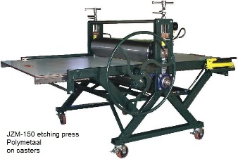
The presses in the JZM-series are very strongly built and include the following features:
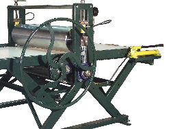
- The bed is driven in these presses, and not the cylinders. This makes of course the construction more complicated, but it has the advantage of eradicating the slippage of the bed. In order to drive the bed, the bed is equipped with two racks (one on each side of the bed). These racks are driven by a gear wheel system.
- Like all our presses, the top roller is fitted with springs. When the spindles are released the roller will lift to facilitate the entry of the plate, lino-cut , woodcut or felt.
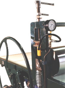
- Hydraulic cylinders have been placed under the spindles. These cylinders are linked with a hydraulic manual pump situated next to the hand wheel. This pump enables the printer to raise pressure on the top roller without much effort. The "normal" pressure spindles can be used to move the top roller upwards or downwards if needed. Once the top roller is in the right position, the pressure is built up by activating the manual pump. The maxium force, on each side of the press is 10.000 kgs. This means that, at maximum, the rop rollers is pushed downwards with a force of 20.000 kgs. (= 44.000 pounds). The exact force can be read on a hydraulic gauge. Standard: the two hydraulic cylinders on each side are interconnected, which means that the pressure on both sides of the press is always the same. With this equipment one can perfectly control the printing process, and duplicate, if necessary the exact conditions of an earlier print.
- These presses are fitted with a mechanical "anti overload device". If ,for example, a screwdriver is left on the press bed, this might lead to damage to the cylinders and the drive system. This illustrates the function of the mechanical overload device which is mounted in the main gear wheel. As soon as something blocks the movement of the press bed, this device begins to slip. The torque at which the device begins to slip, must be adjusted, by the printmaker.
- Each of the four "feet" of these presses are fitted with a mechanical system to enable one to set up these presses correctly in an easy way. Being level is of course of importance. More important however is the correct positioning between the side frames and the rollers.
|
|
|