|
Lithographic presses, JL-series. Polymetaal. Assembly instructies.
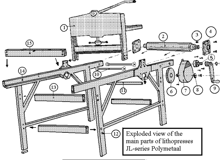
This drawing shows the main parts of the lithographic presses JL-series, in "exploded view".

Normally the client receives the press in assembled state.
The only parts that might have been taken off, for transport reasons are :
1. The pressure system (1.) that should be mounted on top of the press. Just let this part slide between the two side frames (the lever bar on the same side as the drive system, parts 5 through 9) and bolt it together again.
2. Also for transport reasons, the crank and the metal cover of the gearing might be taken off. If that is the case;
a. If the main toothed wheel (6.) is not in place, insert the short key (3.) into the slot of the roller (2.) which is already in position between the side frames.
b. Slide ther main toothed wheel over the shaft of the roller ans secure the wheel by mounting the ring (8.) with a bolt.
c. Mount the auxilary shaft (5.) onto the side frame with four screws (tighten them with Allan-keys).
d. Bring the steel gearing cover in place. Secure it with three small hexagon bolts.
e. Put some grease onto the auxilary shaft (5.) and slide the crank over the shaft. Secure the crank with a ring and screw.
Description of the assembly of a litho press.
- Attach the tube (15.) loosely between the sideframes nr. (14.) and (12.). The spring and buffer must be in the top part of the tube. Use M10 Allen screws. To not tighten these screws. Bringing this tube in is just way to keep the side frames standing up which is easier for the rest of the assembly.
- Bring the roller in place. The roller has a short shaft and a longer shaft. Insert the shafts into the round holes in the side frames. This requires some "spreading" of the side frames. This is possible if the screws of tube (15.) have not been fully tightened. Once the roller is in place the sideframes (12 and 14) can be brought back into normal position.
- The four tubes that have number (13.) can be put into place with Allen screws , as well as the two or three bars (10.)(quantity depends upon model). Now all the screws can be tightened.
- Slide the bearing blocks (4.) over the shafts, and secure them with M12 hexagonal bolts. Bring also the round (distance) bar (11.) into place. Use also for this bar M12 bolts. If all the main bolts are tight the roller can be secured by tightening two little screws in the sleeve of the bearing blocks.
- Bring now the main gear wheel into place. Insert first a short key into the slot of the roller. Now you can slide the gear wheel over the shaft and secure it with a ring and a bolt.
- Bring the auxilary shaft (5.) into place with four M8 Allen screws.
- Bring the cover (7.) into place and secure this with three small M6 bolts.
- Grease the shaft of the auxilary shaft and slide the scrank (9.) over the shaft and secure it with a ring and a screw.
- Clean the roller (2.). For safety reasons the roller is packed with grease paper and plastic tape. Make a very small cut in the plastic tape which allows you to peal off this material. The roller must be cleaned from grease with a solvent and must be clean and dry before use.
The bed of the litho press has not been shown on the exploded view for clarity reasons. Now the bed must be brought into the press between the two side frames. The side of the bed with the grip must be on the side of the buffer in tube number (15.) Adjust the hight of the bars (10.) which is possible since they are mounted in slotted holes in the side frames. There should always be some play between the white plastic rollers on these bars and the bed. This play is needed in order to be sure that the bed has always a good contact with de main roller. If this contact is not optimal, it might result in slippage. |